An SD card connection is a row of flat pads on the card and a matching row of spring contacts in the socket on your board. The card is the standard part; the socket is what you have to choose. Card dimensions, contact assignments and bus speeds on this page come from the SD Association SD Physical Layer specification. Every KINGCONN figure comes from the engineering drawing published on the part page.
SD, miniSD and microSD: the card sizes
The SD Association defines these form factors, and they are not interchangeable in a socket:
- SD — 32.0 × 24.0 × 2.1 mm, the full-size card with the write-protect slider.
- miniSD — 21.5 × 20.0 × 1.4 mm. Obsolete in new designs; you still meet it in legacy equipment.
- microSD — 15.0 × 11.0 × 1.0 mm, the card most modules use today.
An adapter shell lets a microSD card sit in an SD socket. That is a mechanical adapter only: it re-routes the pads, it does not change what the card can do.
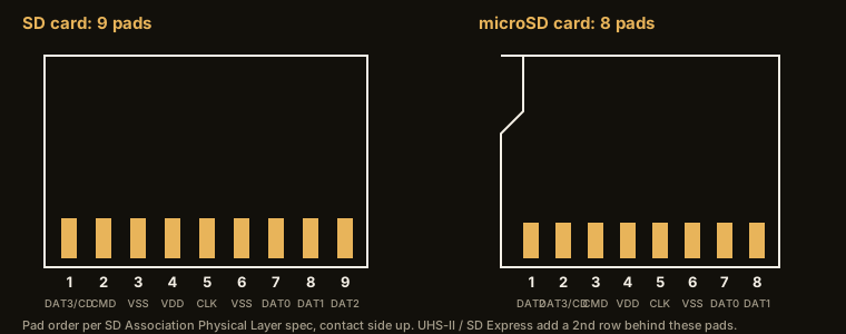
SD and microSD pinout
| Pad | SD card | microSD card |
|---|---|---|
| 1 | CD / DAT3 | DAT2 |
| 2 | CMD | CD / DAT3 |
| 3 | VSS | CMD |
| 4 | VDD | VDD |
| 5 | CLK | CLK |
| 6 | VSS | VSS |
| 7 | DAT0 | DAT0 |
| 8 | DAT1 | DAT1 |
| 9 | DAT2 | — |
The socket brings each pad out to a terminal, and the card-detect and write-protect switches add terminals the card never touches. Route from the socket drawing, not from the card table: socket makers number terminals in their own order. In SPI mode a host uses only CMD, CLK, DAT0 and DAT3; in SD 4-bit mode all 4 data lines carry data and DAT3 doubles as card detect on insertion.
Why "TF card" and microSD mean the same slot
TF (TransFlash) was the original name of the format before the SD Association adopted it. A part described as a TF card socket, a TF port or a T-Flash connector accepts a microSD card — KINGCONN uses either name inside the same series, for example 7TFCN-F0-0018 and 7MSDP-F0-0028. If a datasheet says TF, read microSD.
Bus generations: how many contacts the socket needs
| Bus | Card pads | Socket rows | Max bus speed |
|---|---|---|---|
| SD (default / high speed) | 9 | 1 row | 25 MB/s |
| UHS-I | 9 | 1 row | 104 MB/s |
| UHS-II | 17 | 2nd row, 8 pads | 312 MB/s |
| UHS-III | 17 | 2nd row, 8 pads | 624 MB/s |
| SD Express 7.0 (PCIe 3.0 ×1) | 17 | 2nd row carries PCIe | 985 MB/s |
| SD Express 8.0 (PCIe 4.0 ×1 / ×2) | 17 / 25 | ×2 needs a 3rd row | 1,969 / 3,938 MB/s |
A full-size SD card carries 9 contacts, miniSD carries 11, and microSD carries 8. UHS-II cards add a further row of pads behind the original row, which takes a full-size SD card to 17 contacts in total; a UHS-II socket needs that added row and a layout that treats the pairs as a high-speed channel. SD Express re-uses the UHS-II row for a PCIe lane, and SD 8.0 with 2 lanes adds a 3rd row. A card always falls back to what the socket can connect, so the socket you fit sets the ceiling of the product's card speed.
Socket contact counts do not always match the card. Published counts across the KINGCONN microSD family run from 8 to 11 positions: versions that bring out a card-detect switch have terminals the card itself never touches. 7TFCN-F0-0126 is published at 9 positions, 7MSDP-F0-0037 at 11. Firmware that can tell "no card" from "card failed" needs that switch, so decide it before layout, not after.
Push-push, push-pull and hinge: the socket mechanism
The mechanism decides how the user gets the card back out, and it is the part of the selection that the card standard says nothing about.
- Push-push — insert to latch, push again to eject. No lever clearance, positive tactile latch. 7MSDP-B0-2210 is the push-push part rendered on our homepage.
- Push-pull (normal / no-push) — the card is pulled straight out. Fewer moving parts, shorter body, and the card cannot be launched out by a knock. 7TFCN-F0-0126 is a no-push socket at 1.15 mm profile.
- Hinge (flip / top-mount) — a lid folds down over the card. Used where the card is fitted at assembly and rarely swapped, such as 7MSDH-F0-1012.
The 3 numbers to read off the drawing
Profile height is usually the binding constraint: the KINGCONN microSD family publishes 1.15, 1.28, 1.45, 1.5 and 1.68 mm, and the full-size SD family 2.85 and 2.95 mm. Durability is published at 3,000, 5,000 or 10,000 insertion cycles depending on the model — specify the high class when the card is a user-replaceable medium (dashcam, data logger, POS), not a factory-fitted card. Contact and housing material: contacts are copper alloy or phosphor bronze, housings LCP rated UL94V-0, RoHS compliant.
KINGCONN SD and microSD sockets
The catalog lists 15 full-size SD sockets and 19 microSD (T-Flash) sockets, plus SD 4.0 (UHS-II) dual-row parts and the SD 7.0 / 8.0 Express family. For the selection question rather than the format question, read the SD card connector selection guide or the microSD connector selection guide; for the newer media, microSD generations and combo sockets and SD Express sockets. Send your height limit, mechanism and duty cycle to service@kingconn.com.tw and the Taoyuan R&D team will shortlist against the drawings.
Sockets for each card size and mechanism
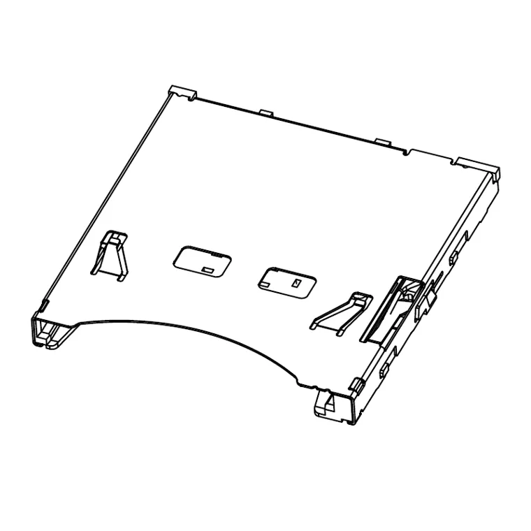 7SDCN-F0-1012SD PUSH H:2.85mm
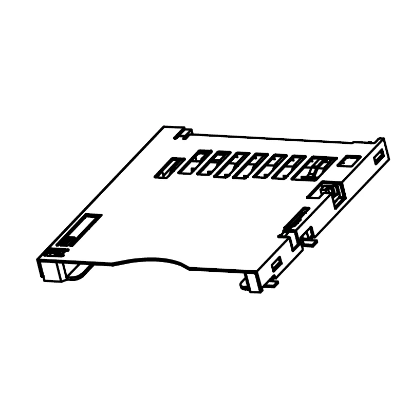 7SDCN-F0-0026SD CONN REVERSE TYPE PUSH PUSH
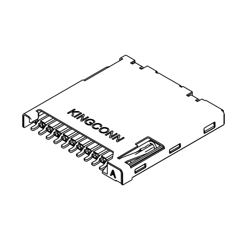 7MSDP-B0-2210microSD 10u" Push-Push Connector with post
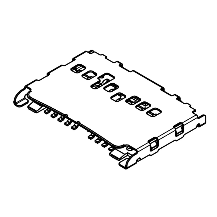 7TFCN-F0-0126Micro SD NO push H1.15mm
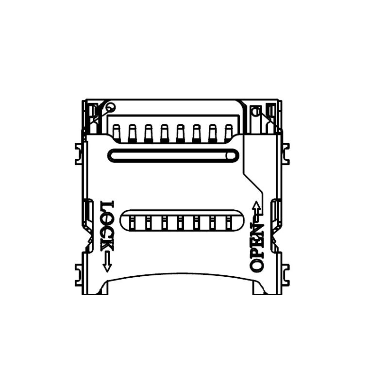 7MSDH-F0-1012Micro SD CONNECTOR HINGE TYPE
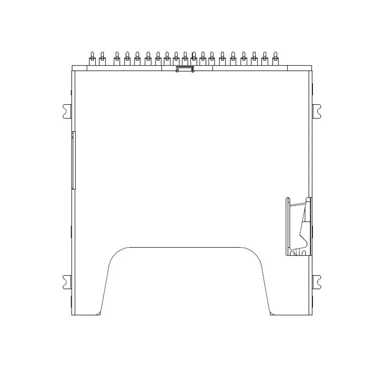 7SD40-FA-0000SD4.0 Top, Push/Push Type,H 3.00mm
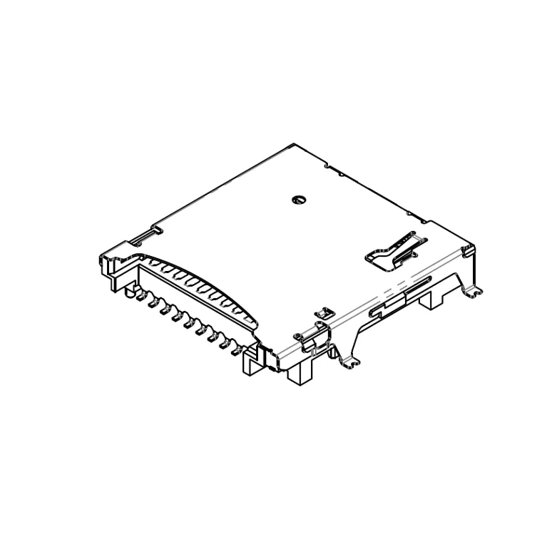 7MSD4-F0-0003MICRO SD 4.0 PUSH H:1.63mm SMD
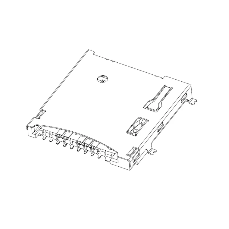 7MSD8-F0-0001MICRo SD8.0 PUSH H:2.27mm
Full-size SD push-push and reverse, microSD push-push, push-pull and hinge, SD 4.0 (UHS-II) and microSD Express dual-row sockets.
FAQ
Can an SD socket and a microSD socket be used interchangeably?
What are the 9 SD card contacts?
What is the microSD pad order?
Push-push or push-pull socket?
What happens when a UHS-II or SD Express card goes into a plain socket?
Standards referenced:
- SD Association SD Physical Layer specification (card sizes and contact counts)
- SD Association SD Physical Layer specification: contact assignment (SD 9 pads, microSD 8 pads), UHS-II 2nd row, bus speeds
- SD Association SD Express (SD 7.0 / SD 8.0 / SD 7.1 microSD Express) PCIe lanes and transfer rates