RJ45 is the everyday name for the 8P8C modular jack used for Ethernet — 8 positions, 8 contacts. The name is borrowed: the original RJ45 registered jack was a telephone interface with different keying. Nobody in the industry will misunderstand you, but a drawing that says 8P8C is being precise. Pin assignments on this page follow ANSI/TIA-568; pair usage and Power over Ethernet follow IEEE 802.3. KINGCONN figures come from the drawings published on the part pages.
The 8 pins and the 4 pairs
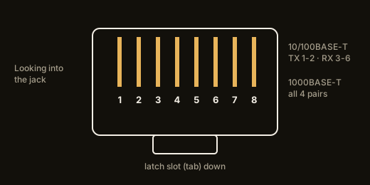
Looking into the jack with the latch slot down, the contacts are numbered 1 to 8 from left to right. The cable is 4 twisted pairs, and TIA-568 assigns them so that pins 3 and 6 belong to the same pair even though pins 4 and 5 sit between them. That split pair is not a mistake — it keeps the jack backward compatible with older telephone wiring, which is why you must never rewire 3 and 6 to be adjacent.
Pairs on pins 1 and 2, and on 3 and 6, carry 10BASE-T and 100BASE-TX. 1000BASE-T uses all 4 pairs in each direction at once, so the pairs on 4 and 5 and on 7 and 8 stop being spare the moment the link negotiates gigabit.
T568A and T568B pinout
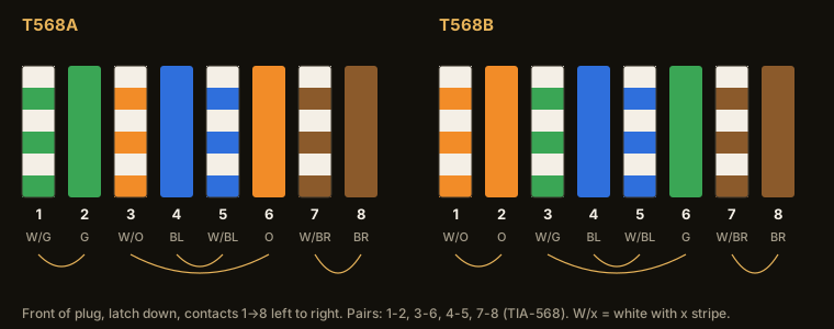
| Pin | T568A | T568B | Pair | Use |
|---|---|---|---|---|
| 1 | white/orange | white/green | pair 1-2 | TX+ (10/100) |
| 2 | orange | green | pair 1-2 | TX− (10/100) |
| 3 | white/green | white/orange | pair 3-6 | RX+ (10/100) |
| 4 | blue | blue | pair 4-5 | 1000BASE-T only |
| 5 | white/blue | white/blue | pair 4-5 | 1000BASE-T only |
| 6 | green | orange | pair 3-6 | RX− (10/100) |
| 7 | white/brown | white/brown | pair 7-8 | 1000BASE-T only |
| 8 | brown | brown | pair 7-8 | 1000BASE-T only |
TIA-568 defines 2 wiring schemes. They differ only in that the green and orange pairs are swapped. Either scheme works as long as each end of a cable uses the same scheme. Mixing schemes end to end produces a crossover cable, which modern equipment auto-corrects and which therefore hides the wiring error until you connect something that does not. Pick a scheme for the site and put it on the drawing.
Terminating a plug: the checks that matter
Strip the jacket only as far as the load bar needs, untwist each pair as little as the plug allows, order the 8 wires per the table above, push them fully home so every wire shows at the plug tip, then crimp. Test with a wire-map tester, not by "it links": a gigabit port will link on a miswired 4-5 / 7-8 and fail later under load. A jack terminated on a punch-down block follows the same colour order; the block is printed with T568A and T568B, so mark which is in use.
Category, bandwidth and reach
| Category | Bandwidth | Typical reach |
|---|---|---|
| Cat 5e | 100 MHz | 1000BASE-T, 100 m |
| Cat 6 | 250 MHz | 1000BASE-T 100 m; 10GBASE-T 55 m |
| Cat 6A | 500 MHz | 10GBASE-T, 100 m |
The jack has to match the category of the installation. A Cat 6A link that ends on a Cat 5e jack is a Cat 5e link. On the board side that means the jack's internal pair separation and shielding options have to be chosen for the speed the PHY will actually run.
Power over Ethernet through the jack
| Standard | PSE output | Power at PD | Pairs used |
|---|---|---|---|
| 802.3af (Type 1) | 15.4 W | 12.95 W | pairs 1-2 / 3-6 (Mode A) or 4-5 / 7-8 (Mode B) |
| 802.3at (Type 2, PoE+) | 30 W | 25.5 W | same, either 2 pairs |
| 802.3bt Type 3 (PoE++) | 60 W | 51 W | all 4 pairs |
| 802.3bt Type 4 | 90 W | 71.3 W | all 4 pairs |
PoE puts DC on the same pairs that carry data. The current passes through the jack's contacts and, on an integrated jack, through the centre taps of its transformer. So a jack that will deliver or receive PoE has to be specified for it — this is not something you can add later with a different cable. 7RJ45-A0-1005 is published as a 1000BASE tab-down jack with transformer, LEDs and PoE support.
Integrated magnetics: the choice that changes your BOM
Ethernet needs transformer isolation between the PHY and the cable. You can put discrete magnetics on the board, or buy a jack with the transformer inside it. The integrated jack costs more per piece and saves board area, placement steps and a set of layout rules that are easy to get wrong.
KINGCONN publishes each style. 7RJ45-F0-0002 is a plain jack; 7RJ45-A0-1005 is the 1000BASE jack with transformer above; 7RJ45-F0-0049-1 is a 100/1000BASE jack with transformer.
Tab-up, tab-down, LEDs and port count
Tab orientation decides which way the cable latch faces on the finished panel, and it is fixed by the part: 7RJUS-F0-0008 is a tab-up part that also carries a USB 2.0 port in the same body, for panels where the 2 interfaces sit together. Jacks with LEDs bring the link and activity indicators out through the front bezel, so no separate light pipe is needed. Port count is part of the housing: 1x1 and 2x1 versions exist in the catalog.
Mounting is through-hole or SMT — 7RJ45-F0-1101 is the SMT part. Through-hole is still normal for panel-edge jacks because the pin retention takes the cable insertion force. A sealed circular version is listed for outdoor equipment.
Durability and materials
KINGCONN RJ45 jacks are published at 750 mating cycles minimum. That number is low next to a memory card socket, and it is the right order for the application: a fixed installation sees the cable inserted rarely. Housings are glass-filled PBT or PBT with LCP rated UL94V-0, contacts are copper alloy, RoHS compliant.
KINGCONN RJ45 jacks in the catalog
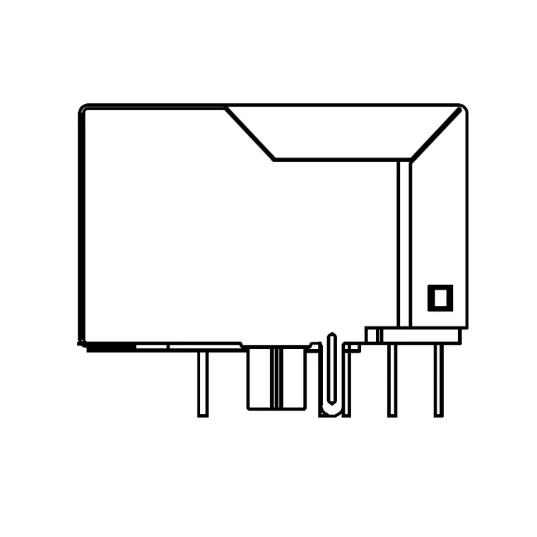 7RJ45-A0-1005RJ45 Connector With Transfomer 1000Base Tab-down 1x1 Port with LED with PoE
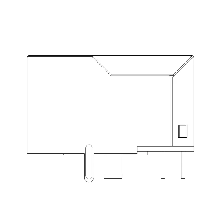 7RJ45-F0-0002RJ45 JACK
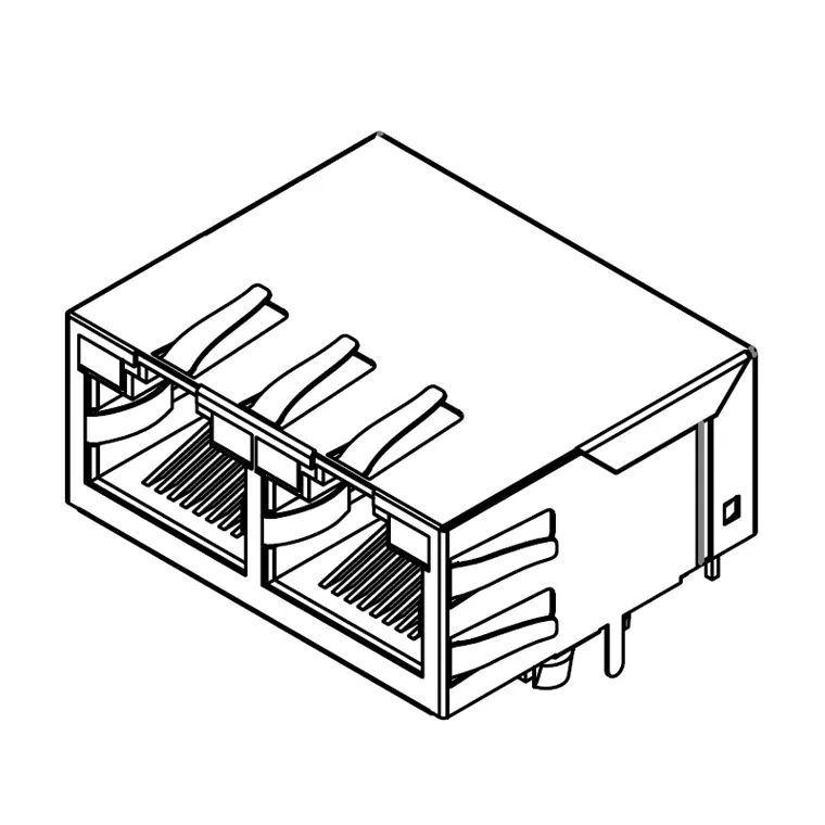 7RJ45-F0-0049-1RJ45+TRANSFORMER 100/1000 BASE WITH
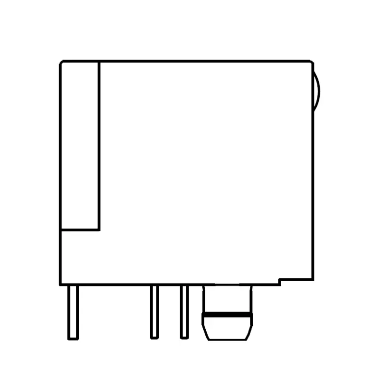 7RJ45-F0-0072Unshielded RJ45 Modular Jack, Through Holp Type, with LED, Prots
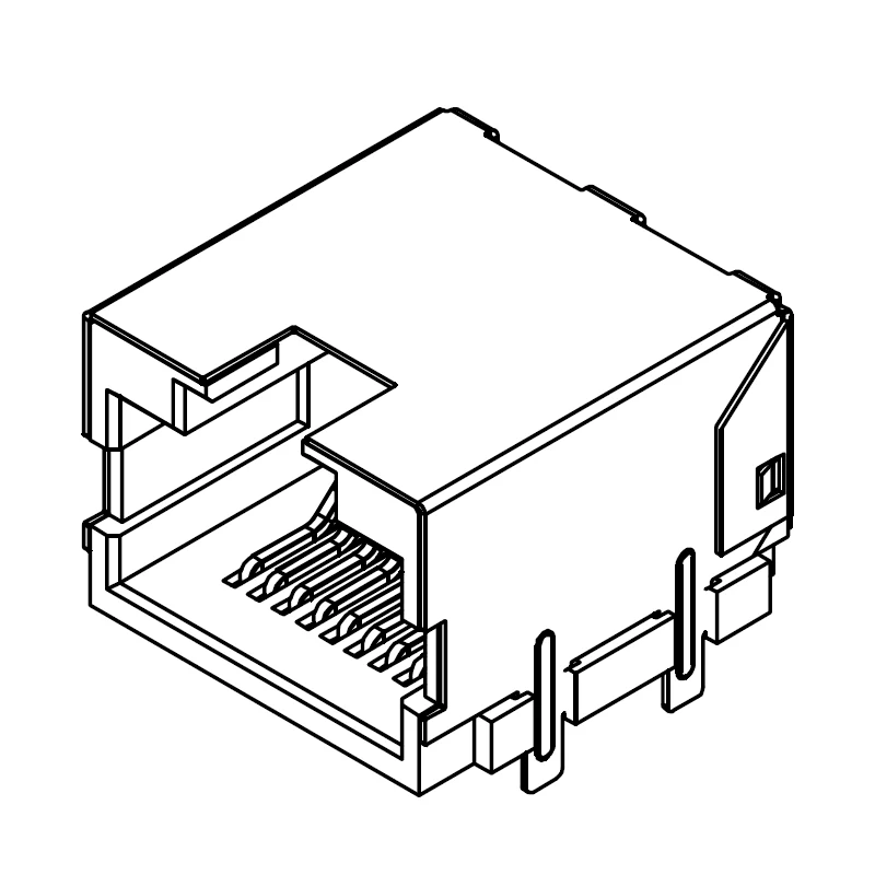 7RJ45-F0-1101RJ45 SMT
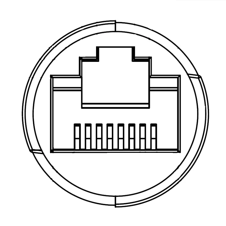 7RJ45-F0-7001RJ45 Circular Waterproof IP67 Female Connector
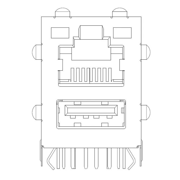 7RJUS-F0-0008RJ45+USB2.0 Connector With Trans former 1000Base Tab-UP 2X1 with LED
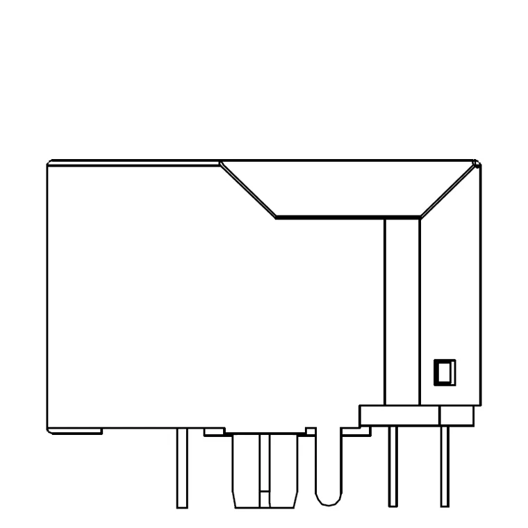 7RJ45-F0-0091RJ45 Connector With Trans former 1000Base Tab-down 1X1 Port with LED
Plain jacks, jacks with transformer and LEDs, PoE and 1000BASE versions, SMT, IP67 sealed and the RJ45+USB combined body.
KINGCONN RJ45 jacks
The catalog lists 9 RJ45 parts, shielded and unshielded, with and without transformer. For the wider board-end I/O question see industrial I/O connectors, or the networking equipment solution page for how these sit alongside the rest of a switch or gateway build. Send your speed, PoE and panel requirements to service@kingconn.com.tw.
FAQ
Is T568A or T568B better?
How are RJ45 jack pins numbered?
Why does gigabit Ethernet need all 8 wires?
What is an RJ45 jack with integrated magnetics?
Do I need a special RJ45 jack for PoE?
Standards referenced:
- ANSI/TIA-568 (T568A and T568B pair-to-pin assignments, 8P8C)
- IEEE 802.3 (10BASE-T, 100BASE-TX, 1000BASE-T pair use; 802.3af/at Power over Ethernet)
- IEEE 802.3af / 802.3at / 802.3bt Power over Ethernet (PSE and PD power classes)
- ANSI/TIA-568 category bandwidth and IEEE 802.3 reach (Cat 5e / 6 / 6A, 100 m / 55 m)